
| External Interfaces/API |   |
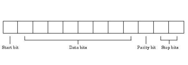
The serial data format includes one start bit, between five and eight data bits, and one stop bit. A parity bit and an additional stop bit might be included in the format as well. The diagram below illustrates the serial data format.

The format for serial port data is often expressed using the following notation
For example, 8-N-1 is interpreted as eight data bits, no parity bit, and one stop bit, while 7-E-2 is interpreted as seven data bits, even parity, and two stop bits.
The data bits are often referred to as a character because these bits usually represent an ASCII character. The remaining bits are called framing bits because they frame the data bits.
Bytes Versus Values
The collection of bits that comprise the serial data format is called a byte. At first, this term might seem inaccurate because a byte is 8 bits and the serial data format can range between 7 bits and 12 bits. However, when serial data is stored on your computer, the framing bits are stripped away, and only the data bits are retained. Moreover, eight data bits are always used regardless of the number of data bits specified for transmission, with the unused bits assigned a value of 0.
When reading or writing data, you might need to specify a value, which can consist of one or more bytes. For example, if you read one value from a device using the int32 format, then that value consists of four bytes. For more information about reading and writing values, refer to Writing and Reading Data.
Synchronous and Asynchronous Communication
The RS-232 standard supports two types of communication protocols: synchronous and asynchronous.
Using the synchronous protocol, all transmitted bits are synchronized to a common clock signal. The two devices initially synchronize themselves to each other, and then continually send characters to stay synchronized. Even when actual data is not really being sent, a constant flow of bits allows each device to know where the other is at any given time. That is, each bit that is sent is either actual data or an idle character. Synchronous communications allows faster data transfer rates than asynchronous methods, because additional bits to mark the beginning and end of each data byte are not required.
Using the asynchronous protocol, each device uses its own internal clock resulting in bytes that are transferred at arbitrary times. So, instead of using time as a way to synchronize the bits, the data format is used.
In particular, the data transmission is synchronized using the start bit of the word, while one or more stop bits indicate the end of the word. The requirement to send these additional bits causes asynchronous communications to be slightly slower than synchronous. However, it has the advantage that the processor does not have to deal with the additional idle characters. Most serial ports operate asynchronously.
| Note When used in this guide, the terms "synchronous" and "asynchronous" refer to whether read or write operations block access to the MATLAB command line. Refer to Controlling Access to the MATLAB Command Line for more information. |
How Are the Bits Transmitted?
By definition, serial data is transmitted one bit at a time. The order in which the bits are transmitted is given below:
The number of bits transferred per second is given by the baud rate. The transferred bits include the start bit, the data bits, the parity bit (if defined), and the stop bits.
Start and Stop Bits
As described in Synchronous and Asynchronous Communication, most serial ports operate asynchronously. This means that the transmitted byte must be identified by start and stop bits. The start bit indicates when the data byte is about to begin and the stop bit(s) indicates when the data byte has been transferred. The process of identifying bytes with the serial data format follows these steps:
Data Bits
The data bits transferred through a serial port might represent device commands, sensor readings, error messages, and so on. The data can be transferred as either binary data or ASCII data.
Most serial ports use between five and eight data bits. Binary data is typically transmitted as eight bits. Text-based data is transmitted as either seven bits or eight bits. If the data is based on the ASCII character set, then a minimum of seven bits is required because there are 27 or 128 distinct characters. If an eighth bit is used, it must have a value of 0. If the data is based on the extended ASCII character set, then eight bits must be used because there are 28 or 256 distinct characters.
The Parity Bit
The parity bit provides simple error (parity) checking for the transmitted data. The types of parity checking are given below.
Mark and space parity checking are seldom used because they offer minimal error detection. You might choose to not use parity checking at all.
The parity checking process follows these steps:
For example, suppose the data bits 01110001 are transmitted to your computer. If even parity is selected, then the parity bit is set to 0 by the transmitting device to produce an even number of 1's. If odd parity is selected, then the parity bit is set to 1 by the transmitting device to produce an odd number of 1's.
 | Serial Port Signals and Pin Assignments | Finding Serial Port Information for Your Platform |  |